Introduction:
Hello world! Few years ago, a new chip came to the market which started a new revolution! Yes, i am talking about the ESP8266. This chip is way more powerful in terms of CPU architecture, clock frequency, flash size and power consumption if we compare it with existing arduino boards that usually contains Atmel's AVR controllers.
 |
| ESP-01 Module |
Actually i bought this ESP-01 modules few years back which was originally flashed with good old serial AT command firmware. Over the time, I figured out that the same chip can be directly programmed through the Arduino IDE. This feature is so amazing that you can practically use all existing arduino libraries and the same IDE to program the ESP8266 according to your need by flashing your own arduino sketch. (Word of caution: It will remove your existing AT commands firmware from the chip)
Okay, but why DeAuth?
[ First of all you must read this, if you don't know anything about deauthentication attack. ]
After experimenting a lot with typical IoT stuff like thingspeak API or Blynk platform, I stopped working with ESP8266 for few months. During this period, I learned about stuff related to penetration testing of Wi-Fi. If you want to know more about cracking WPA handshakes click here to know more because its certainly out of the scope of this post.
After experimenting a lot with typical IoT stuff like thingspeak API or Blynk platform, I stopped working with ESP8266 for few months. During this period, I learned about stuff related to penetration testing of Wi-Fi. If you want to know more about cracking WPA handshakes click here to know more because its certainly out of the scope of this post.
I thought, it would be great to build a device which is able to deauth all nearby WiFi devices instead of running deauth attack from terminal by entering bunch of commands. Thus, once again, i decided to pull out my ESP8266 module from the drawer after long time!
Setting it up..
To build your own deauth device, you will need following stuff:
- Any ESP8266 module (ESP-01 is smallest & cheapest! I recommend this)
- Arduino IDE (Above v 1.6.5)
- FTDI / Another Arduino / Any USB to Serial programmer.
Now, lets assume you have all three things which i mentioned above. Then first you need to add ESP8266 board to your IDE.
Instructions for adding ESP8266 to Arduino IDE:
Please strictly follow all the instructions given below to avoid compilation errors!
- Start Arduino and open Preferences window.
- Enter http://arduino.esp8266.com/stable/package_esp8266com_index.json into Additional Board Manager URLs field. You can add multiple URLs, separating them with commas.
- Open Boards Manager from Tools > Board menu and find esp8266 platform.
- Select the version 2.0.0 you need from a drop-down box.
- Click install button.
- Don't forget to select your ESP8266 board from Tools > Board menu after installation.
- Go to the file
Packages > esp8266 > hardware > esp8266>2.0.0> tools> sdk > include folder and replace existing user_interface.h file with this modified file. - Go to Packages > esp8266 > hardware > esp8266>2.0.0> libraries > ESP8266WiFi folder
- Replace existing ESP8266WiFi.cpp with this and ESP8266WiFi.h with this file.
Congrats, you have completely installed ESP8266 SDK with promiscuous mode support by using above modified files. The modified files enables promiscuous mode which is supported but not activated by deafult SDK.
Programming ESP:
For programming ESP8266 through arduino, select proper board settings from arduino IDE and make connections of ESP8266 module with your USB programmer like this.
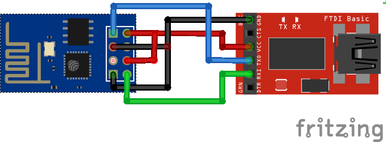 |
| ESP8266 programming mode |
Usually, for all my projects, i prefer to write my own code because its fun! But for this project, I am going to use a ready made code available on this GitHub link (Thanks to RandDruid) because there is no point in re-writing the new code to generate exactly same format of deauth packets generated by the available code. Though, I have added few more functionalities like Inbuilt LED blink on transmitting each deauth packet to provide visual feedback without need of serial monitor. Feel free to modify the code as per your need.
Flash the given code through arduino IDE. If you are getting connection related erros while flashing, make sure CH_PD pin is tied to Vcc & try playing with connections of RESET & GPIO0 pins ;)
You will definitely figure it out!
You will definitely figure it out!
Making a battery-mount:
My primary objective was to build the battery-powered super compact deauth device, so i soldered everything on a general purpose PCB. All you need is a battery clip connected to an ESP through a voltage regulator.
First i tried to use a 3.3v regulator for ESP but it didn't worked for me! I guess that was due to low output current of voltage regulator than ESPs requirement. Then i did a little trick here, Even though ESP8266 works at 3.3V and it's recommended to operate on 3.3V, I powered it with 5V regulator (LM7805) & it worked like a charm!! Even though it gets a bit warm after usage, it is still working fine :)
Here are some images of prototype so that you will understand how compact it is:
 |
| Top side of PCB |
 |
| Battery clip is glued to solder side |
 |
| Working prototype - Blue LED blink indicates deauth frame transmission |
Now, you can carry this little WiFi snipper anywhere along with you and it will continuously keep deauthenticating all devices from all routers which are in its range.
I hope you already know the purpose of writing this post is purely intended for knowledge sharing and penetration testing to improve network security. Any unethical use of this type of device will not be appreciated.(Particularly by your neighbours!)
Your sniper is now ready to hunt. Happy DeAuthenticating!! :)
The json file doesn't offer a version 2.0.0 from the drop down box, only generic ESP8266 module. Can you clarify this step please?
ReplyDeleteAny version higher than 2.0.0 will do the same work. Just don't forget to copy given cpp & h files as they are tweaked to enable promiscuous mode which is commented by default.
DeleteHey, I tried compiling but I get errors - https://pastebin.com/a84P0UjZ
ReplyDeleteCould you please have a look? Thank you!